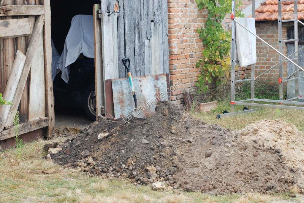
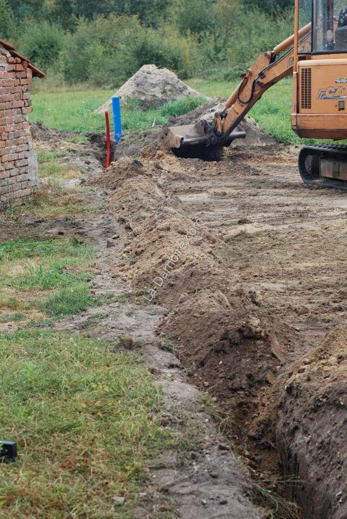
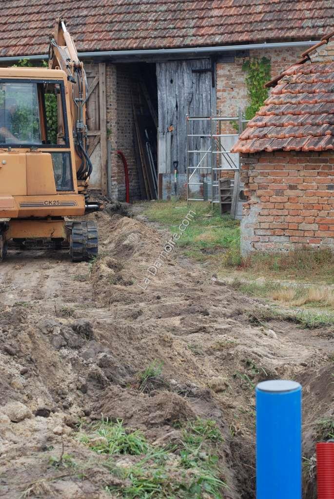
As previously mentioned, the borehole is some 15 metres from the house. Winter temperatures here can get as low as -20°C, so any pipework needed to be well protected. Fortunately LSS knew a local earthmoving contractor, so we arranged for him to pay us a visit with his mini-digger. An 80cm deep trench was soon dug between the borehole and the closest access point to the house, which was the barn door.
I then installed a length of corrugated plastic tube, 63mm in diameter. This will carry both the 32mm diameter polyethylene "blue band" water pipe (designed for potable water) and the electric cable to power the borehole pump.
The trench was then backfilled. I'm so glad we didn't have to do this by hand!
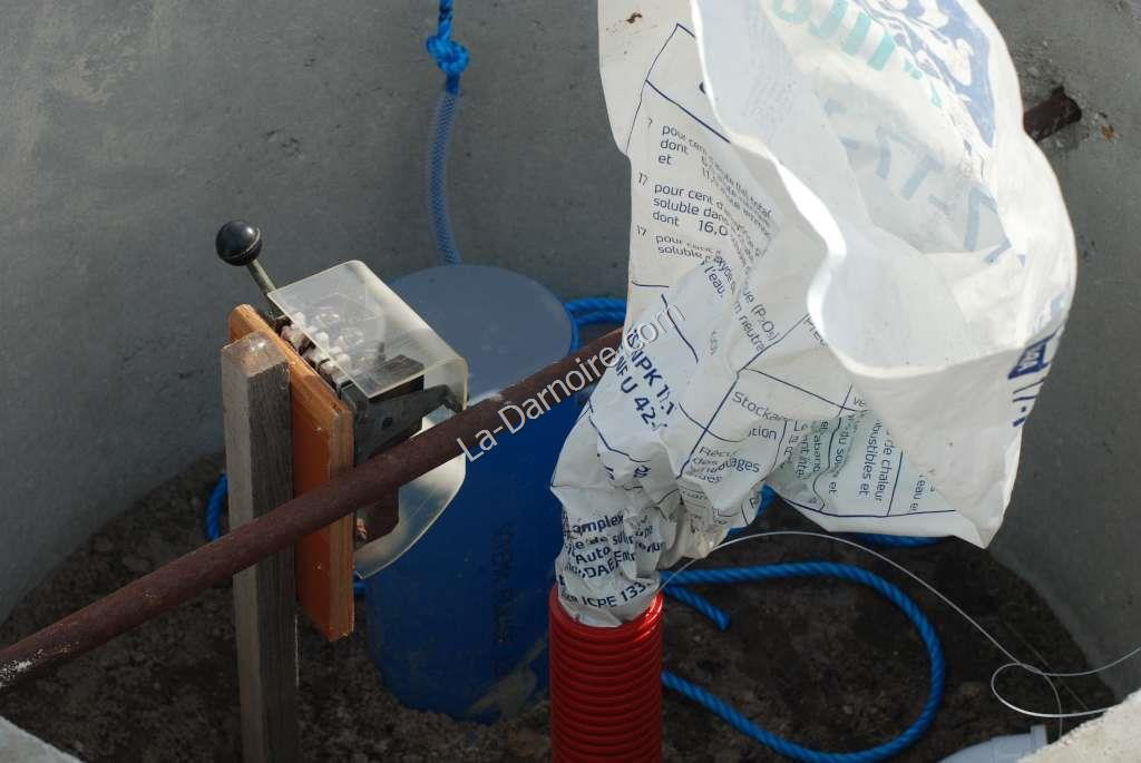
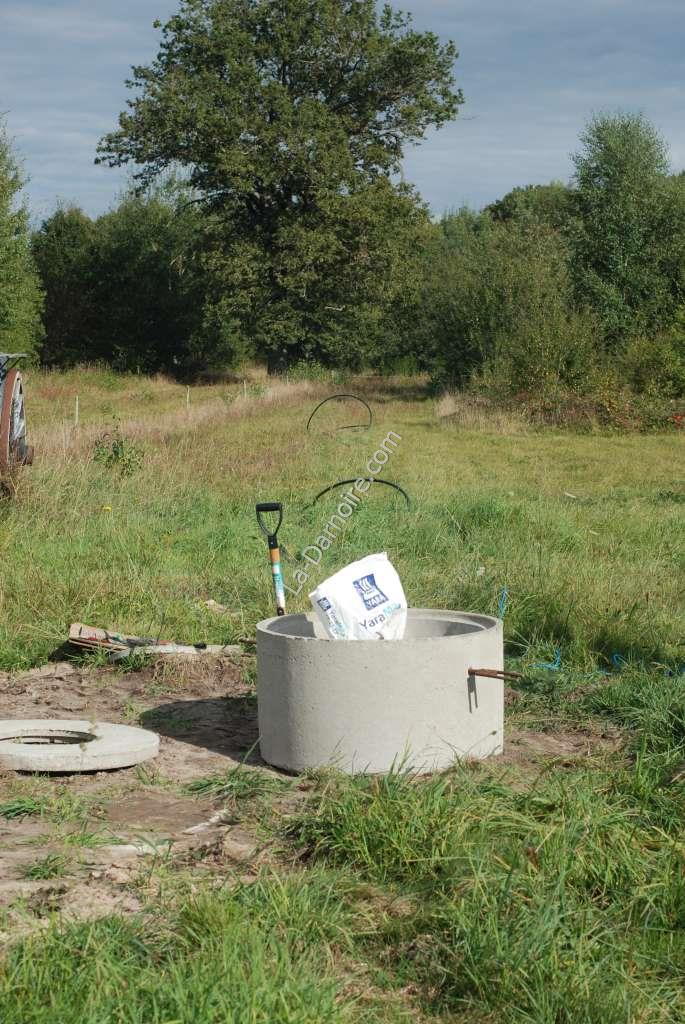
The next item on the shopping list was a cast concrete surround with lid, which will provide frost protection to the borehole itself. A stout steel bar provides an anchor point for the rope which will hold the borehole pump at 40 metres depth. Obviously one needs to make sure it is very securely tied! I had trimmed the top of the borehole pipe to a more suitable height, and also plugged the red pipe with a plastic bag until such time as the polyethylene pipe is installed. The old manual electric switch you see here was later removed; being replaced by a simple male plug and female socket.
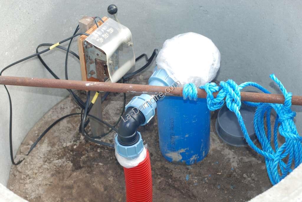
In the next photo I have attached a 42 metre length of nylon rope to the borehole pump, and am coiling it ready for feeding the pump down the borehole. The pump itself is in the cardboard box on the left, but is unfortunately hidden from view.
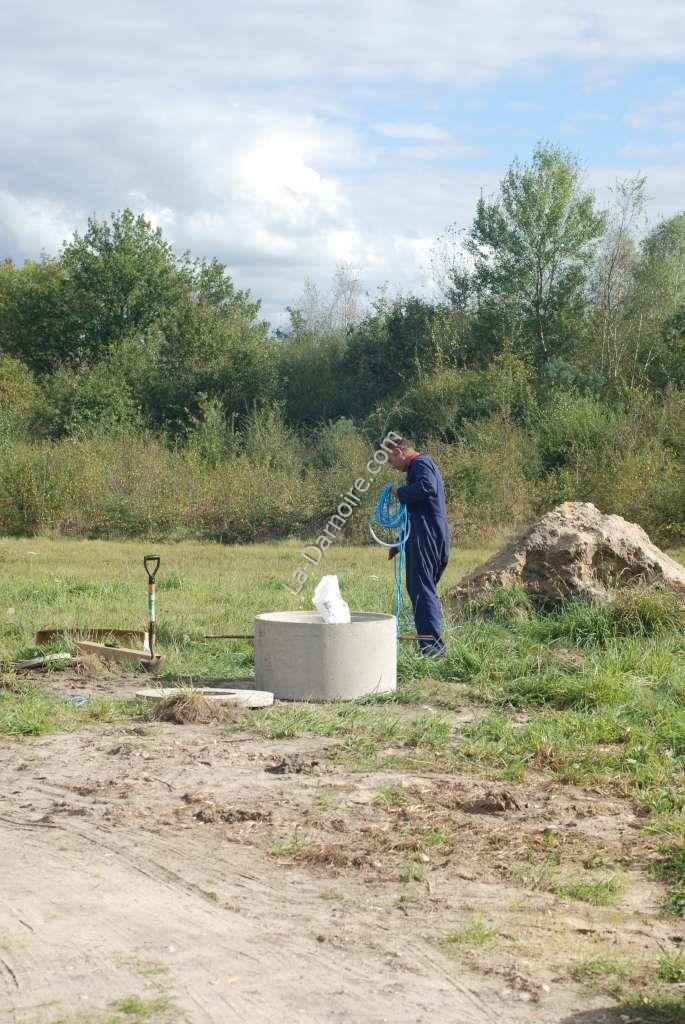
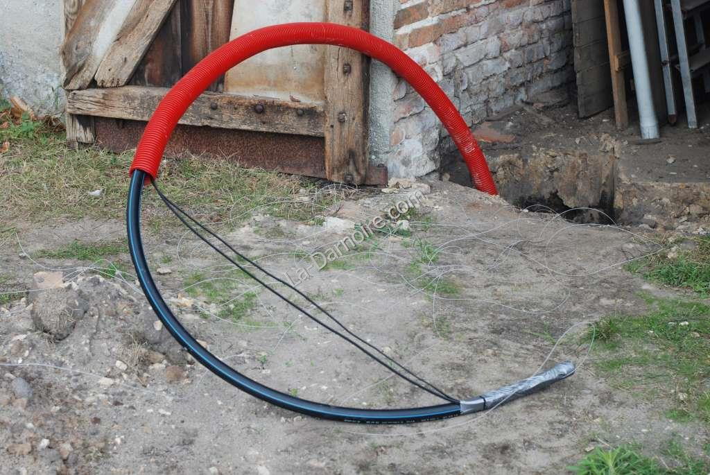
If you look carefully you can see the coils of the 40 metres of thick-walled polyethylene pipe laid out in the adjacent field ready for insertion. A non-return valve was installed in the pipe as well. When the pump is in place, this valve will be at a depth of 10 metres below ground level. (This was recommended in the documentation of the borehole pump). The electric cable for the ZDS borehole pump was attached to the polyethylene pipe every 5 metres or so by using cable ties. Feeding this lot down the borehole pipe was like wrestling with an octopus; the pipe kept re-coiling itself. As both LSS and I were involved with this task, I'm afraid there isn't a photo of the actual event!
Another length of polyethylene pipe was then fed through the underground tube from the borehole to the barn, together with the electricity supply cable. I actually installed two electric cables in the pipe; one will lead from the manometer on the upstairs pressure vessel to the borehole pump; the other is a spare to provide another power point at the borehole for future use.
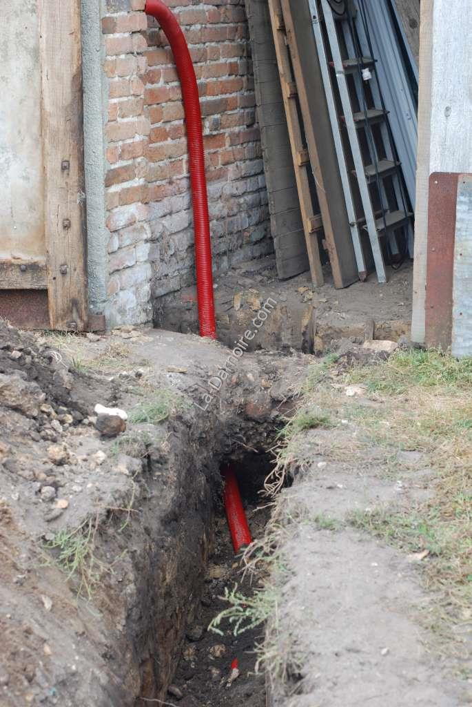
The red pipe is attached to the angle of the wall in the barn and leads to the upper floor. At the borehole, the electric cables were connected up, and the two polyethylene pipes joined together with unions. One should use as few bends as possible; but there was no other option but to use two 90° bends here.
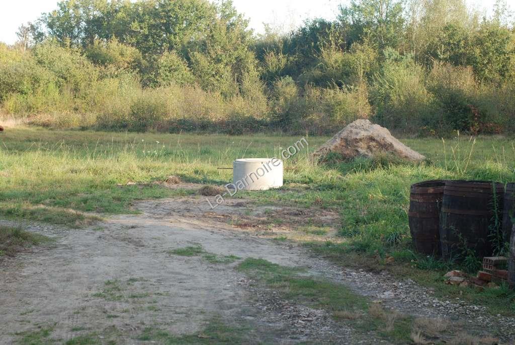
The concrete lid was then placed on the borehole surround, and the outside water installation was complete. (I later placed some layers of glass fibre within the concrete surround as further insulation). I could now transfer my attention to the water supply indoors. In this photo you can see that of the three piles of earth excavated before the borehole drilling, only one remains.
The reason I opted to install the water supply to the upstairs level was purely a reason of space. The house currently has three rooms; kitchen, lounge, and bedroom. There just isn't enough room on the ground floor, until such time as we can refurbish the attached barn. I had wondered whether there would be sufficient water pressure if we just had an open vented tank upstairs. However, calculating that water pressure increases by only 1 bar for every 10 metres in height, the answer to this was obviously no. In order to provide a decent water pressure at the tap, we therefore required a pressure vessel.
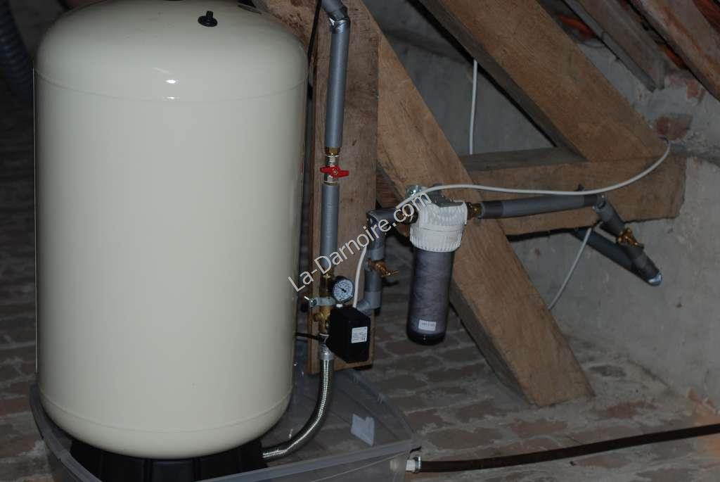
We purchased a USA-made Challenger model. With a five-year guarantee, and a capacity of 200 litres, it is simply a sealed tank with a membrane. A manometer (pressure gauge) is connected inline, and is set so that it controls the borehole pump. If the pressure falls below 1 bar, the pump is switched on. The pump switches off again when the pressure in the tank reaches 2.5 bar.
I installed the pressure vessel in a plastic tray in case of leaks. A hosepipe will channel any unexpected water from the plastic tray, through the wall, to the outside. In the photo you can see the insulated pipe carrying water from the borehole on the right. There is another non-return valve installed at the point at which the pipe reaches the upper floor. I also installed an inline water filter. Once everything was tested, the pressure vessel itself was insulated with a layer of glass fibre.
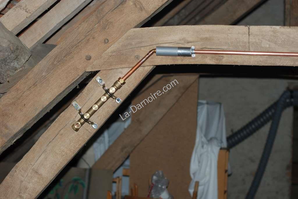
The final part of the water supply was then installed. This takes the form of a manifold. The copper pipe from the pressure vessel to the manifold runs along one of the roof support beams. I chose a 5-port manifold which will be connected as follows:
- Water supply to the thermal store
- Hot water coil supply
- Kitchen cold water supply
- Future bathroom cold water supply
- Spare
With the house now supplied with running water, the next item on the agenda was how to deal with the water once it had been used. This is detailed in the next section, Greywater Reedbed.